2013-11-24 13:30
ok, first, several links:
As mentioned elsewhere,
"ARM CPU is the not main CPU - it's only a co-processor to the VideoCore GPU. When the RaspberryPi starts,
a GPU blob is read from the SD card to the L2 cache and executed. This code then brings up all the important peripherals
(RAM, clocks etc) and starts the ARM CPU. Then the 2nd stage bootloader or some operating system itself can be run on ARM CPU."
According to this and
other sources, RPi boot process looks like this:
- GPU Core
- first stage bootloader, which is stored in ROM on the SoC
bootcode.bin (loader.bin merged) - the 2nd stage bootloaderstart.elf - the main GPU codeconfig.txt - file is read by the GPU before the ARM core is initialisedfixup.dat - is used to configure the SDRAM partition between the GPU and the CPUcmdline.txt - file for passing arguments to the Linux kernelkernel.img - The OS kernel to load on the ARM processor
For board to boot you need an SD-card with FAT32 partition, and files mentioned above placed in a root of this partition.
Binaries are available here in boot folder. Actually there are more of them there:
fixup_cd.dat, start_cd.elf - cut-down versions of the above files, used when GPU memory is set to 16 MB, which in result disables some GPU
featuresfixup_x.dat, start_x.elf - testing versions of the above files, which enable potentially unstable/not-fully-tested/hacky functionality
config.txt and cmdline.txt are just a text files, you can edit them
according to docummentation. kernel.img is usually a linux kernel - the first thing to run on ARM CPU, but it can be an additional
chained boot loader like u-boot, and for our experiments we will use the later.
2013-11-19 15:46
RPi has HDMI and composite video out and 2 USB ports for keyboard/mouse, but this is not very convinient,
when sitting most of the time by a normal workstation. In this case optimal way for user i/o would be serial
console port with USB interface towards PC.
Raspberry Pi has built-in TTL
(Transistor-transistor logic) UART (Universal Asynchronous
Receiver/Transmitter) for serial communication, and it can be connected to PC via external USB-to serial
converter. I bought this one
from DX. It's based on CP210
chip, has 5 pins (+3.3V, TX, RX, GND and +5V). It does not have RTS or DTR line for resetting Arduino, but we don't need it fo RPi.
Linux kernel recognises it out of the box on the PC side by cp210x driver, and creates ttyUSBx interface:
[ 4998.908243] usb 2-2: new full-speed USB device number 3 using ohci_hcd
[ 4999.363425] usb 2-2: New USB device found, idVendor=10c4, idProduct=ea60
[ 4999.363433] usb 2-2: New USB device strings: Mfr=1, Product=2, SerialNumber=3
[ 4999.363437] usb 2-2: Product: CP2102 USB to UART Bridge Controller
[ 4999.363441] usb 2-2: Manufacturer: Silicon Labs
[ 4999.363444] usb 2-2: SerialNumber: 0001
[ 4999.418936] usbcore: registered new interface driver usbserial
[ 4999.418962] USB Serial support registered for generic
[ 4999.419425] usbcore: registered new interface driver usbserial_generic
[ 4999.419430] usbserial: USB Serial Driver core
[ 4999.425099] USB Serial support registered for cp210x
[ 4999.425360] cp210x 2-2:1.0: cp210x converter detected
[ 4999.820368] usb 2-2: reset full-speed USB device number 3 using ohci_hcd
[ 5000.279312] usb 2-2: cp210x converter now attached to ttyUSB0
[ 5000.279312] usbcore: registered new interface driver cp210x
[ 5000.279312] cp210x: v0.09:Silicon Labs CP210x RS232 serial adaptor driver
$ lsusb | grep CP210x
Bus 002 Device 003: ID 10c4:ea60 Cygnal Integrated Products, Inc. CP210x UART Bridge / myAVR mySmartUSB light
For Windows you need drivers avalable from here.
Serial port settings are:
Speed (baud rate): 115200
Bits: 8
Parity: None
Stop Bits: 1
Flow Control: None
Connect GPIO TXD pin on the board to the converters RXD pin, GPIO RXD pin on the board to converters TXD pin,
and GND to GND on both board and converter, leaving both power pins on the converter alone:

We actually can use +5V pin on a converter, connecting it to 5V GPIO pin on the board to feed RPi
from PC's USB via the same connection, instead of using external power via micro-usb connector
on the board - it's sufficient to boot RPi without external USB periferials attached, but the
problem here - we will not see the start of the boot process, as serial interface device is non
existant prior to connecting converter to PC and launching terminal emulator takes time.
Or, alternatively, we can add power switch to the wire between 5V pins.
More info on connecting Pi via serial port is available here.
2013-11-19 02:48
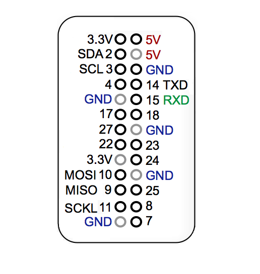
Raspberry Leaf aka GPIO Reference Board, is a small reference card,
mounted on top of the GPIO pins - good thing for humanitarians like me, "an
extremely cheap way to avoid making potentially fatal mistakes when prototyping".
Adafruit sells pretty one, but $2.95 + xN shipping
is kinda overprice for me, so I went printing one myself, taking initial png file from
here.
and tuning it a bit using mad M$Paint skillz (original was little too wide).
This one is for rev.2 boards pinout:
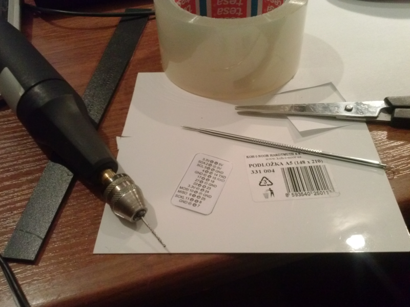
Sticking it with a clear tape to the thin PVC and drilling the holes:
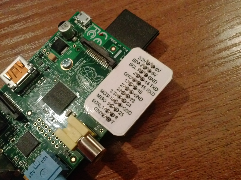
Result is not exactly chef-d'oeuvre of industrial design, but it works:
2013-11-18 21:22
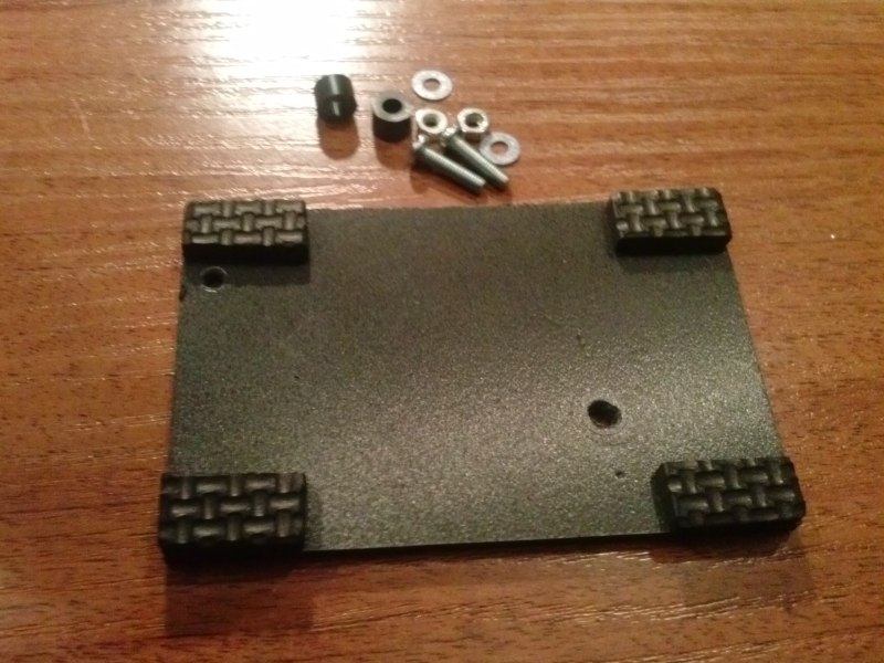
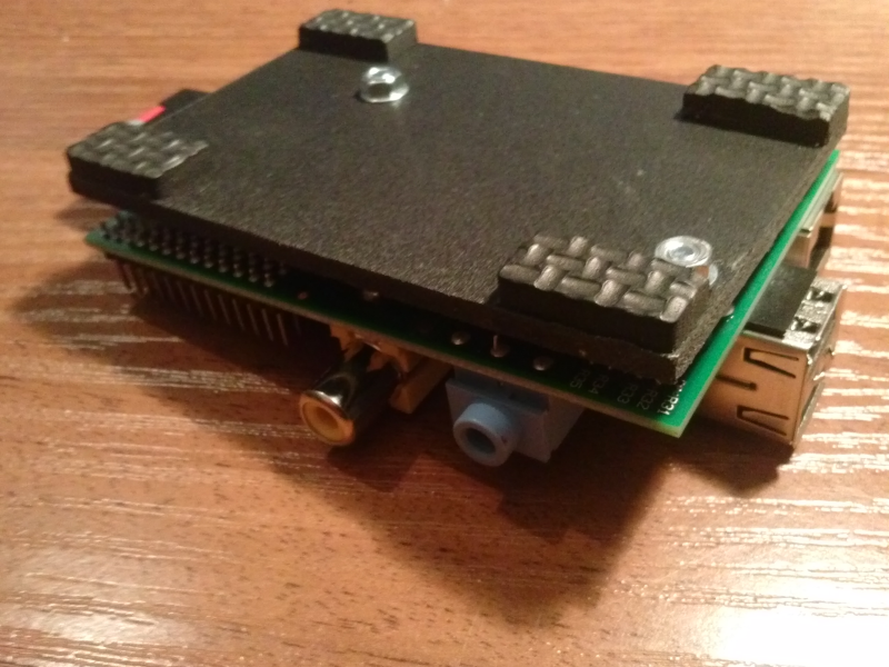
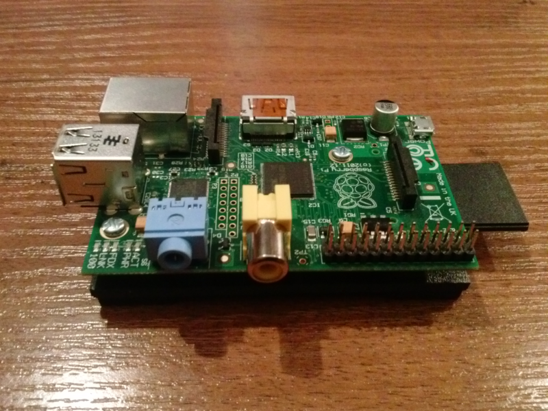
So I finally got some more time to play with the Raspberry Pi.
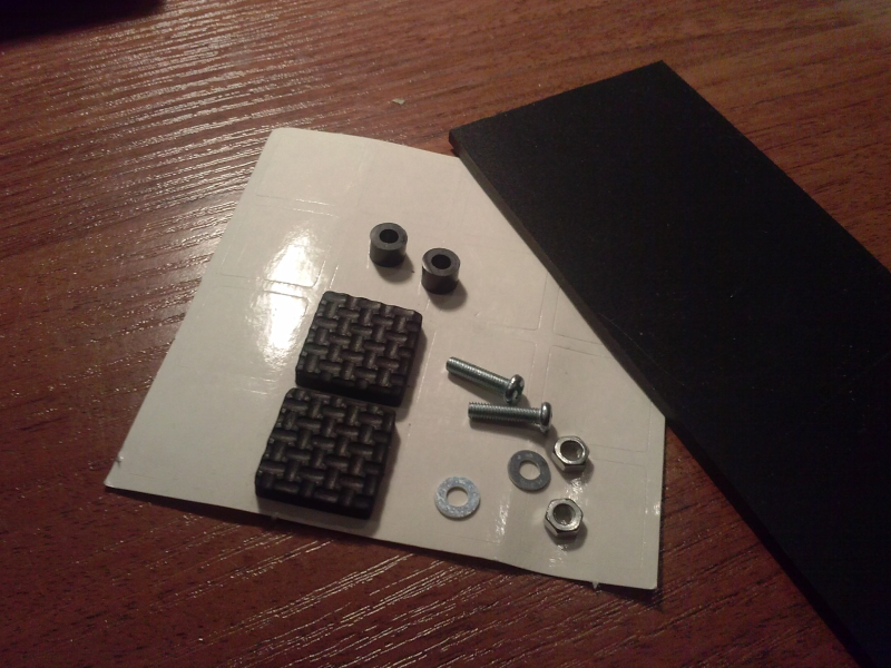
First, out of the 3mm PVC foamboard piece, 2 5mm spacers, 2 M3x12mm screws
with nuts and washers and two furniture sticky pads cut in half,
I've made a base for the board:
2013-10-06 21:13
After cygwin repository structure change, separating architectures, old good vanilla apt-cyg does not work anymore.
Fast dirty fix:
$ sed -i 's@mirror/setup@mirror/x86/setup@' /bin/apt-cyg
Or better use one of the more elegant patches available.